Wednesday, December 21, 2011

Forward skins and cockpit work.

I have have been making progress on the forward fuselage in recent weeks. I installed the floor ribs and then the floor skin was cut, bent, shaped and rivet holes drilled in preparation for its installation. In the 3rd photo below you can also see that I created the center control cover which is held in place by screws instead of rivets so it can be removed.

Click on images to enlarge


Next came prepping the side skins for installation. (These side skins were cut and sized last winter when the fuselage was still on the table.) This is a tedious process as you have to fit, remove, mark the hole locations, then drill holes in one piece, then debur them all. Then repeat the process with the adjoining piece until you have what you are looking for. I countersunk the lower longeron near the spar and dimpled the skin for flush rivet installation where the leading edge rib will be mounted later. I also creased any overlapping skin edges in hopes for a smooth, gapless edge once the rivets are installed.


I have yet to drill the rivet holes near the firewall or along the upper longeron as I still have work to do in these areas.

I then removed these skins so I could work on creating the interior side panels that go between F3 & F5 bulkheads. These panels will be made so I can remove them to have access to the landing gear bolts and rudder pedal cables.

In the series of photos below, you can see that I created a tab at the top of these panels that will sandwich the F5 bulkhead flange near the top. On my bulkheads, I found that the F5 flange becomes too narrow for me to install screws. This tab will make the panel fit snugly with the flange at the top.


In the photo below, you can see that I also created an angle from some .032 aluminum stock to hold the bottom edge of the panels in place. I slid these angles between the floor skin and the outer floor ribs so they can share the same rivets.


I still have some work on all of the above and should have pictures of the final product in the near future.

Tuesday, November 15, 2011

I have a new set of wheels!

Click on image to enlarge


It's a big moment when you get to sit in your creation and and make engine noises! But let's back up and see how I got here.

Once the gear was in place, it was time to assemble the wheels, axles, brakes and wheel pant bracket. I bought everything shown in the pictures below from Great Plains Aircraft Supply. I had drilled the 4 mounting holes months ago. The caliper housing comes to you fresh from the casting mold and needs to be "machined" to allow the calipers to fit inside snugly, but able to slide side to side nicely with out binding. You just use a combination of files and sanding tubes to slowly remove just the right amount of material to get the fit you want.


My axles had a "knob" on the back side of the mounting plate the same diameter as the axle. This is used in other installations, but not on the CX4. You have to grind this "knob" off to make the back side of the axle mounting plate completely flush. I didn't take a photo of this, but you'll figure it out if your axles come with the "knob".

There is a lot of assembly and dis-assembly in this process. You have to create a spacer to keep the wheel the correct distance away from the mounting bolts so as not to rub them on the brake disk. I used a piece of PVC tubing to cut a sample spacer until I found the distance I liked. My spacers were 1.75" long and I made them from .759" ID 4130 steel tubing. I would say this gave me a clearance of approximately 1/8".


Once you have everything the way you want them, you disassemble everything so you can pack the wheel bearings with grease. When you are done with that, you reassemble everything and mark a dot on the axle threads where you want to drill a cotter pin hole to hold the castle nut in place. I was told to only hand tighten the castle nut. Over tightening doesn't allow the wheel to rotate freely.

Also in the photos you can see the piece of aluminum where the wheel pants will be attached later. I used the pattern from the plans and found I had to modify them slightly to fit around my brake assembly. No big deal though.

Next I finished installing the tail wheel. When you tighten the forward bolt it will dent the bottom fuselage skin slightly. This is normal according to Dave Thatcher. I spent an afternoon trying to figure a way to avoid the dent, but the solution eluded me. Mine will have the dent like Dave's does. It is so minor that when you turn it over you don't know it's there.


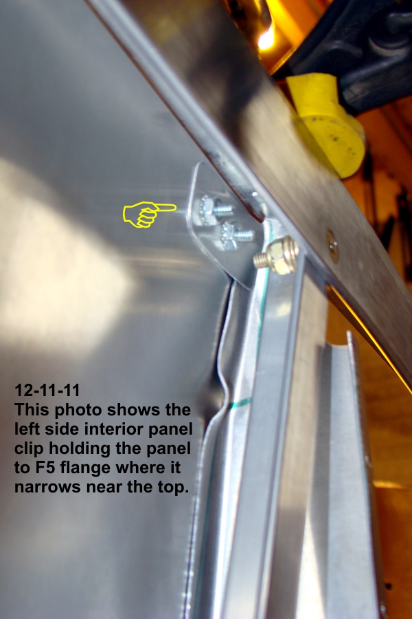
Now it was time to turn it over! My son was the first to sit in it and he liked it. Then it was my turn. Here is where I get to caution the rest of you. It is best not to put too much weight on the seat area until you have attached the side panels. Why you ask? Because when I stepped on to the spar with one foot I heard a loud bang! I took my foot off and looked around and everything seemed to be in place. So I tried again. This time when I place my second foot on the spar I heard another loud bang! I step off and looked around. I still didn't see anything wrong. So I tried again to get in and this time there were no annoying sounds, but when I sat down and look forward, I could see that the single rivet at the top of each F5 bulkhead had popped free from the top longeron. I decided I needed to go on a diet.

I got out and found my two long wood clamps and pulled the lower and upper longerons together and drilled out and replaced the two rivets. I used longer rivets as well. I'll have to wait until the side skins have been installed to make engine noises again.

I have started installing the forward floor ribs so that will be my next update.

Monday, October 31, 2011

Attached forward bottom skin.

I finished shaping and attaching the forward bottom skin. I dimpled and installed flush rivets along the forward edge so that the cowling will lay across it smoothly. The sides are attached in this manner as well because the side skins overlap in this area. The only difference is that I dimpled the bottom skin and countersunk the longeron underneath.


Click on image to enlarge

I'll begin to install the wheels and brakes so I can then turn the fuselage over.

Monday, October 10, 2011

Began landing gear installation.

I began installing the landing gear. I use a laser I bought at Harbor Freight as my main alignment tool. It has magnets on it, so I attach it to a long handled clamp and clamp the clamp to a small work table and place it in front of my project. I use it to align all the center lines from front to rear. I also used a tape measure to check all distances to the tail wheel bolt in the rear. Once I had everything where I thought it should be, I clamped the landing gear to the lower stingers with 4 clamps.

I should mention that I did this twice. The first time was see where the hole locations should be. I then removed the landing gear and drilled 1/8" pilot holes in it with my drill press. Then I re-aligned the gear and drilled those pilot holes through the stringers in the fuselage. Even though I used 4 clamps to hold the gear in place, I also used 1/8" bits, AN3 & AN4 bolts to place in the holes while I enlarged the holes to their final size to accept an AN5 bolt. The idea here is to make sure the holes stay aligned while you are enlarging the other holes. Here are a couple of photos.


Click on image to enlarge

I had seen in other builder photos indicating one needs to be aware of possible interference of the side bolts that hold the side angle support in place between F3 & F5 bulkheads. I happened to be using pan head screws instead of countersunk screws at these locations, so I will be able to remove these screws temporarily to install the gear bolt nuts. Here are a couple of photos showing this situation.


I just noticed that I have mislabled the locations of these bolts. They are the right side, but I have the forward/rear locations reversed from what they should be.

Thursday, October 6, 2011

Installing forward bottom skin.

The last two weekends I have continued working on the forward bottom skins. Everything is going fine, but there is a lot of trial fitting and trimming that has to take place before actually pulling rivets. I have also been preparing to install the landing gear by drilling pilot holes in the gear in preperation to locate it on the fuselage and transfer the hole locations to the lower longerons.

Here are a few photos. As always, look in my photo album for additional photos.


Tuesday, September 6, 2011

Misc. work effort


click on image to enlarge

I did work over the weekend, but didn't really accomplish a whole lot. I worked on shaping and attaching the the channel at F3 and began to install the tail wheel.

Monday, August 29, 2011

Look Ma, no work table!

Click on image to enlarge

This was a big weekend as I was able to remove my fuselage from my work table. I flipped it upside down so that I could finish installing rivets on the underside of the belly skin. These are the rivets that you are not able to get at because of the jigging.


Before I flipped over my project, I cut the exit slots for the rudder cables where they come out of the fuselage in the rear.


Above I am attaching the belly skin to the center section.


Now I'll work on installing the forward bottom skins and install the tail wheel before I flip it over.

Sunday, August 21, 2011

Pulled rivets on fuselage side skins.


click on image to enlarge

Feels good to make progress that you can see. After taking the skins on and off umpteen times to shape, file, debur holes, install cables etc., I was able to pull some rivets on both forward side fuselage skins today. I'm happy with the results.

The plans call for you to put on the left side skin and then pull the fuselage off your jig and table to install the controls before the other side is attached. I had heard that some who had followed these steps found that the fuselage would twist because only one side skin was being install at a time. They would have to remember this and somehow take the twist out before riveting the second side skin in place which usually solved the problem. I decided to install the controls and then rivet both forward side skins on at the same time to avoid the twisting issue. I pulled a few rivets on one side and then went and pulled some on the other until I was done. I left off both the rear skins so I can finish installing the controls. I have some minor things to clean up, but I should be able to pull my fuselage from the table and jig next session.

Sunday, August 14, 2011

Control cables & fuselage skin.


Click on image to enlange

I strung the control cables and started to install the right side skin. I still need to bring the rudder cables out the lower rear skin, but I'll do that before I start pulling rivets.

Friday, July 15, 2011

Working on controls.

Yes, it has been a while since I posted. What have I been doing? Mostly coaching my son's Little League baseball team.

Click on image to enlarge.

Also, if you have been keeping up with the news, the Missouri River basin is being flooded due to excessive snow melt and spring rain fall (so "they" say). The water at Gavins Point dam is being let out at a rate of 160,000 cubic feet per second. My hangar is at Eppley Airfield here in Omaha and is about 400 yards from the levy that holds the water back. They have been successful in keeping the water on the correct side of the levy so far, but I took precautions anyhow. This photo shows me tending to my CX4 wings which I am now storing 7 feet above my hangar floor in the loft of my work bench.


I was able to work on my project recently and I am now working on my control linkage. I installed the elevator push rod and the rudder cables. I am using the hanging rudder pedals and I purchased them from Dave Thatcher and found that I had to raise the hole location where my cable is to go through the F5 bulk head, as my attach points on my rudder pedals were 1.75" higher up on my pedals than what is shown on the plans. The cable was binding at the plans location. After speaking with Dave, it was determined that the higher attach point was done to take out some sensitivity in the rudder. I moved the F5 hole location up just enough to remove the binding in the cable, but kept it at a location that was still under the arm rest. Most builders these days are building the floor mounted pedals, but of course Dave is there to support my efforts. Here are a few photos of my efforts.


I have more photos in my album.

I will have one more weekend to work on my project before heading north to AirVenture. See you there!

Monday, April 4, 2011

Preparing to install left side fuselage skin.

click on image to enlarge

I made fun progress yesterday. For weeks you work on prepping and making parts and visably you don't see any progress. Once you begin to install these parts, you really feel like you have made progress. Yesterday was one of those days. I pulled some rivets to replace the clecos holding the bottom skin in place and the cross bars I installed to keep the sides of the bottom skin from flexing outward. Then I drilled and cleco'd the forward side skin into place. It's starting to look like something!

Saturday, March 26, 2011

Filing! And I don't mean my taxes!

Click on image to enlarge

When you build a fiberglass airplane you do a lot of sanding, with metal airplanes, you file! I used the paper patterns to cut my side panels out. Now I'm just filing them down to final size.

Tuesday, March 1, 2011

Now making side skin patterns.

Click on image to enlarge

I started making patterns for my side skins by using construction paper. This should allow me to get the bottom to line up properly. The panel between bulkhead F10 & F12 is per plans. The panels between the F6 seat back and F10 can be done as one, two or three pieces. I will be doing mine using 2 pieces of skin.

Tuesday, February 15, 2011

Bottom skin attachment continues

I have been working on my project, but it is slow going. Here are a couple of photos which shows my progress.


I had a gap at the bottom of bulkhead F9 & F10 that I didn't think I could "squeeze out" with rivets, so I created spacers to fill those gaps. Here are some photos of the spacers. Notice that I am holding them in place with hot glue until I can turn the fuselage over and install rivets in F9 and the tail spring bolt in F10.


I found trying to get the bottom skin to stay in place at the flange was a challenge. I could not install a cleco or a rivet near the flange because I want to place the side skin on top of the bottom skin and attach the rivet through both pieces. The natural "memory" of the aluminum would flex the skin outward. You can not hold it in place with straps when you have to attach the side skins. I finally decided to attach an aluminum angle to the flange that spans the width of the fuselage at each bulkhead in addition to the angle in between the bulkheads (as called out in the manual) to keep it in place until I can attach the side skins. These angles will remain and don't add very much weight.

I will be cutting and trimming the sides skins in the near future. Progress is being made even if at a slow pace.