Monday, December 3, 2012

Brake Lines & Fuel Pumps

I have been working on my project, but sometimes you get caught up in the details and it doesn't seem like you're making any progress. In fact, you are, because attention to the details makes a better aircraft.

click on image to enlarge
 

I needed to run my brake lines though the lightening holes in the F2 bulkhead and they were rubbing against the edge.  Later I will be running wiring through this bulkhead also. So, I went looking for an edge trim material and finally saw a nice solution on another builders CX4. I can't remember who it was, but thank you! You can see it in the photo above. It is called Grommet Strip and I purchased it from Terminaltown.com as suggested by the other builder (Item #GSNC-1).  It comes in two sizes and this one works on material up to a thickness of .036". I ordered 4 feet and was hoping it came in one piece so I could cut it to length. Unfortunately, it came as four, one foot pieces. It is designed for circular holes for which the F2 bulkhead holes are not. They are made of a hard plastic and rely on the memory of the material to stay in place within a circle hole.  This might work for our oblong F2 bulkhead holes if it came as one piece, but it takes two pieces of the 12" strips to fill the circumference. To help keep it in place, I used some of the high temp clear caulking I was using to fill the holes around my firewall edge.  The caulking keeps the trim in place quite nicely.

This next photo shows the F2 bulkhead from the rear.  You can see that I used a larger tube to protect the brake line where it comes through the F2 bulkhead and 3 layers of heat shrink to protect it from the upper longeron hole it goes through. There is little to no movement at the point it goes through the longeron, but I wanted some protection from rubbing anyway.


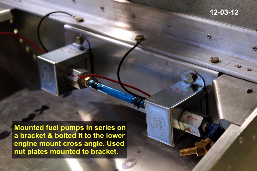
I have been working on my fuel system also and decided on installing two pumps in series.  To minimize vapor lock situations, I also decided to install them on the back side of the firewall where they will remain cooler.   Instead of mounting them directly on the firewall, I created a mounting bracket from some scrap .062 aluminum I had laying around. I just bent a 90 degree flange as a mounting point. I drilled 3 holes in the lower engine mount cross angle for AN3 bolts and installed nut plates on the underside of the bracket flange so that it could be removed to work on or replace a pump.  The photos below show this installation.


Up next is the gascolator installation and running the fuel lines through the firewall.

Thursday, October 25, 2012

Tank Cover & Front Skin ready for rivets

I finished the tank cover and I'm ready to pull rivets for the side skins and instrument panel top skin.  However, I will not pull the rivets in hopes that Santa will bring me some more instruments. It just seems to me that waiting till the very last moment to shut this area up is the best way to proceed.  I also want to work out my fuel pump locations and not having the side skins in place would also allow for more working area.  Here are a few photos.
 
Click on image to enlarge


The photo below shows I also installed my electical bus on the front side of bulkhead F2.


I have more photos in my photo album if you would like to view them.
 
Next I will be working on the tail feathers and writing my wish list to Santa.

Saturday, October 6, 2012

Finished installing fuel filler door.

I finished installing my fuel filler door today and I am quite satisfied with my creation and work.  Here are a few photos:

Click on image to enlarge


I was concerned that the door would not line up with the cover skin and in the corners it did not. However it was quite simple to bend the corners slightly with my fingers and thumb to get the door to match up nicely with the cover skin.
 
Next up is to finish installing the tank cover skin itself and then on to the skin that spans F2 to F4.

Tuesday, October 2, 2012

Creating a Fuel Filler Door

If you remember, I created a fuel tank that would not fit under the tank cover skin and have the filler cap exposed as the plans call out for.  Instead I had to lower the tank and now have to create a door to expose the fuel filler cap. Here are a few photos of what I'm working on.
 
Click on image to enlarge
 
 
I settled on a 5"x5" opening in the shape of a "D".  I looked into using a DZUS or Camloc fasteners but they both require a relatively expensive specialized tool for inserting the grommets.  I bought a Hartwell H-5000-2 latch from eBay but once it arrived, I discovered I didn't have the necessary clearance between the tank cover skin and the tank for it to be used.  So I searched the internet and found a rotating, spring loaded latch that I thought would work for this application.  I found it at Granger and it came in three sizes.  The medium sized one is the one I purchased (part # 4RPY8) for about $10.00. Here are a couple of photos showing it in the open & closed positions.


This is what it looks like from the top.
 
 
As you can see, it has a very low profile as well.
 
I made the supporting shelf from two layers of .032 aluminum.  I had to use two layers in order to account for the thickness of the door hinge which was .032 as well. Once I got the two pieces shaped the way I wanted them to be, I used spray adhesive to hold the two pieces together until they could be riveted into position around the door opening. You should be able to see the two layers in the 1st photo above. Here are a some photos of the door temporarily in place.


Next  up is to drill and rivet the shelf and hinge to the tank cover skin then to finish the installation of the skin itself. The door will need a slight arch in it to match the curve of the skin.  Wish me luck on figuring this out.


Friday, September 28, 2012

Installation of my radio tray.

I finished the installation of my radio tray for my iCom A200 radio. The photos below show that I tried to make it as removable as possible from below because once the skin between F2 & F4 (the instrument panel) is riveted in place, the only access is from below or through the openings in the F2 bulkhead.
 
 
Click on image to enlarge
 
 
I attached a 1.5" x.0625" angle, purchased from Lowe's, to each side of the tray because the tray itself could not be attached from below.  The tray mounting holes were on the sides. I removed some material from the angles to lighten it and to create clearance for other instruments. Then I used an aluminum channel, also purchased from Lowe's, as a rear tray support that spans width wise between the upper longerons. I used nut plates on both the tray angles and the channel so the screws could be removed from below. In the front, I stuck some window foam insulation to the tray's underside which allows it to rest on the angle I'm using at the bottom of the panel for my switches and breakers. This puts the tray at the approximate height behind the panel hole where the radio slips in from the front. I left the screws at the rear channel slightly loosened until the radio is in place and then I'll tighten the screws at the rear support.


This is how it looks from the front.
 
 
I'm currently working on the fuel tank cover and a hinged access door for the fuel filler. I'll have another update to document this progress soon (I hope).


Monday, August 27, 2012

Panel & electrical planning


As usual, I came home from AirVenture with brochures of all the latest electronics.  Before Little League interrupted my building process, I was working on the tank cover, which means I'm not too far from installing the skin between bulkheads F2 & F3 (the instrument panel). I had been thinking about my fuel system as well because I'm getting close to installing the side panels as well. Now is the time to start thinking about the consequences of installing these skin panels because after they are installed, access gets limited. So I started thinking about my panel. After much deliberation, I have settled on what you see in the photos that follow.

Click on image to enlarge.


The first thing I did was to modify the electrical diagram in the plans to fit my needs.  This led me to see that I needed a terminal block to distribute the power to various items in my aircraft.  I searched the web and found this one.  I think it will do the job nicely and I plan to mount it to the front side of F2 bulkhead.


Next I found some nice toggle switches that display a red LED light when in the "on" position. I found these at Waytech.com.  I then designed and created a breaker and switch panel out of 1.5"x1.5"x.0625" alum. angle. You can see it in the photo above and in the photo below where it will be installed under the F3 panel bulkhead.  It will be made removable so you can get at the wiring with out removing the instrument panel.


The photo above shows a mock up of my "wish" panel.  I better start my Christmas list soon because the only item I currently have is the comm. radio. Who knows, by the time I actually purchase any of these items, there might be better, less expensive alternatives. OK, maybe better alternatives, but never less expensive ones!
 
 
It's good to be back building again.

Saturday, July 28, 2012

Time to start building again!

Little League is over and I just got back from AirVenture. Time to get back to building my CX4!

Friday, March 30, 2012

Hanging rudder pedals installed.

I was looking over my recent build photos and I realized I had not made an entry about installing my rudder pedals.

Most people building CX4's these days have switched to the floor mounted rudder pedals, but I had purchased the original hanging ones from Dave and I kind of liked the feel of this version, so I stuck with them.

I made some modifications to the plans that I think improve the installation (Of course! They're my ideas.). I didn't think the sleeves that are to be riveted in place on either side of each pedal to hold them in place allowed much flexibility for an error (and we know I'm prone to making such errors) or any adjustment that might need to be made. So, I purchased 4 countersink set stops from McMaster to hold the pedals in place. They weren't cheap at $5.00 each, but neither would be a mis-drilled rivet hole.

Click on image to enlarge

You can see these set stops in the photo above on either side of the upper swing tube of the rudder pedal. These step stops have two set screws. I found I had to sand the inside of the set stops to get them to fit over the steel tube. I'm glad I purchased them as there was quite a bit of fiddling with the pedal to get it in just the correct location to swing past the side of the fuel tank.


In the photo above you can see the angle I used for a mounting bracket for the side to side steel tube for which the pedals use to swing from. The plans call for you to use a conduit hanger, but the hole in this angle captures the steel tube nicely. I actually had to cut another steel tube to a more appropriate length than the one Dave sent with the pedals. The original length was too short.


I rounded off the outside corner of this angle so that it fit snugly under the upper longeron. I secured the angle with two AN3 bolts. One of the bolts is shared with the angle that lies across the longerons to hold the fuel tank in place.  You can see it in the photo above.

I'm generally pleased with the installation.

Tuesday, March 20, 2012

It's time for Little League.

My posts will slow down for a while as I am once again coaching my son's Little League team.  This goes through the end of June. Wish us luck!

Wednesday, February 22, 2012

Get Smart use to say: "Missed it by that much."

When you make mistakes, you just find solutions. As I build a piece or build a part, I always try to anticipate how this step is going to effect things down the road. Sometimes you understand the cause and effect, and sometimes you don't. I built my fuel tank about a year ago.  There has been some modifications to the tank plans and I have 3 plan revisions to work from. The original tank was only 9.5 gallons, but that wasn't large enough for some builders, so Dave Thatcher created a 10.5 gallon drawing for someone and I got a copy of this. Then when the Europe equivalent of the FAA didn't like how Dave had installed his tank, Dave modified the tank and how it was installed/mounted. At about the same time, Dave developed the floor mounted rudder pedals; again in response to a Europe request. The fuel tank dimensions changed with these modifications, but remained a 10.5 gallon tank. I had bought the hanging rudder pedals and after reviewing the floor mounted version, decided to stick with the hanging pedals. My plan was to use version 1 of the 10.5 gallon tank but use the new mounting method which involved side to side straps that would cradle the tank from underneather. The tank cover would be sandwiched between 2 gaskets at the fuel filler flange. Everything was going to plan until I rasied the tank top to be level with the flanges where the tank cover would be attached. That's when "I missed it by that much." I found my tank corners sticking out beyond edge of the fuselage.

click on image to enlarge

So, in a panic I called Dave and then a local friend, Steve Bennett who stopped by to see what could be done. Between the conversations I had with these two, a "plan B" was developed. I would simply buy longer bolts to lower the tank and I would create a strap to go over the top of the tank to hold it in place. I would then create a fuel access door for the tank cover. This seems to be working out and no snags have presented themselves.


First, I came up with a paper pattern for the top strap that I liked and transfered it to some scrap .020 aluminum. I cut out the perimeter using my band saw. Then I clamped the piece to a scrap board, drilled a hole in the interior and cut the circle out using a jig saw. The .020 aluminum is a little flimsy so I used the board to help with filing the edges.


Once the piece was cut and filed, I mark the locations where I wanted bends and proceeded to make the bends one at a time. I would trial fit the piece after every bend and mark the next bend location. The bottom photo is the final product. I drilled & tapped two holes on each side in the upper longeron for 8-32 screws. To help spread the load, I created two 1/16th inch thick plates to go on top of the strap on each side (as shown in the above photo).


This photo shows the top strap installed. I plan to install aluminum tubing over the 4 bolts that hold the lower straps on so that the nuts can be tighten. The tubes would serve as spacers and this would essentially trap the tank in place.

I'm thinking about creating a cup of some sort to go under the fuel cap flange to catch any drops of fuel so they don't spill inside the cockpit. Look for an update describing what I came up with.  I have an automotive gas cap door on order as I felt this might make a more "professional" installation than me making one myself.

In concert with the installation of the tank, comes the installation of the hanging rudder pedals, but that's the topic for my next post.

Sunday, February 19, 2012

Still working, but no pictures

I haven't posted for a while, but I have been working on the plane. I just haven't taken the time to post anything. Once I get to a good point I'll post some pictures, but not tonight.

I have been working on installing the fuel tank and rudder pedals. This is tedious work, but I'm making progress.  Stay tuned...