Monday, August 27, 2012

Panel & electrical planning


As usual, I came home from AirVenture with brochures of all the latest electronics.  Before Little League interrupted my building process, I was working on the tank cover, which means I'm not too far from installing the skin between bulkheads F2 & F3 (the instrument panel). I had been thinking about my fuel system as well because I'm getting close to installing the side panels as well. Now is the time to start thinking about the consequences of installing these skin panels because after they are installed, access gets limited. So I started thinking about my panel. After much deliberation, I have settled on what you see in the photos that follow.

Click on image to enlarge.


The first thing I did was to modify the electrical diagram in the plans to fit my needs.  This led me to see that I needed a terminal block to distribute the power to various items in my aircraft.  I searched the web and found this one.  I think it will do the job nicely and I plan to mount it to the front side of F2 bulkhead.


Next I found some nice toggle switches that display a red LED light when in the "on" position. I found these at Waytech.com.  I then designed and created a breaker and switch panel out of 1.5"x1.5"x.0625" alum. angle. You can see it in the photo above and in the photo below where it will be installed under the F3 panel bulkhead.  It will be made removable so you can get at the wiring with out removing the instrument panel.


The photo above shows a mock up of my "wish" panel.  I better start my Christmas list soon because the only item I currently have is the comm. radio. Who knows, by the time I actually purchase any of these items, there might be better, less expensive alternatives. OK, maybe better alternatives, but never less expensive ones!
 
 
It's good to be back building again.

Saturday, July 28, 2012

Time to start building again!

Little League is over and I just got back from AirVenture. Time to get back to building my CX4!

Friday, March 30, 2012

Hanging rudder pedals installed.

I was looking over my recent build photos and I realized I had not made an entry about installing my rudder pedals.

Most people building CX4's these days have switched to the floor mounted rudder pedals, but I had purchased the original hanging ones from Dave and I kind of liked the feel of this version, so I stuck with them.

I made some modifications to the plans that I think improve the installation (Of course! They're my ideas.). I didn't think the sleeves that are to be riveted in place on either side of each pedal to hold them in place allowed much flexibility for an error (and we know I'm prone to making such errors) or any adjustment that might need to be made. So, I purchased 4 countersink set stops from McMaster to hold the pedals in place. They weren't cheap at $5.00 each, but neither would be a mis-drilled rivet hole.

Click on image to enlarge

You can see these set stops in the photo above on either side of the upper swing tube of the rudder pedal. These step stops have two set screws. I found I had to sand the inside of the set stops to get them to fit over the steel tube. I'm glad I purchased them as there was quite a bit of fiddling with the pedal to get it in just the correct location to swing past the side of the fuel tank.


In the photo above you can see the angle I used for a mounting bracket for the side to side steel tube for which the pedals use to swing from. The plans call for you to use a conduit hanger, but the hole in this angle captures the steel tube nicely. I actually had to cut another steel tube to a more appropriate length than the one Dave sent with the pedals. The original length was too short.


I rounded off the outside corner of this angle so that it fit snugly under the upper longeron. I secured the angle with two AN3 bolts. One of the bolts is shared with the angle that lies across the longerons to hold the fuel tank in place.  You can see it in the photo above.

I'm generally pleased with the installation.

Tuesday, March 20, 2012

It's time for Little League.

My posts will slow down for a while as I am once again coaching my son's Little League team.  This goes through the end of June. Wish us luck!

Wednesday, February 22, 2012

Get Smart use to say: "Missed it by that much."

When you make mistakes, you just find solutions. As I build a piece or build a part, I always try to anticipate how this step is going to effect things down the road. Sometimes you understand the cause and effect, and sometimes you don't. I built my fuel tank about a year ago.  There has been some modifications to the tank plans and I have 3 plan revisions to work from. The original tank was only 9.5 gallons, but that wasn't large enough for some builders, so Dave Thatcher created a 10.5 gallon drawing for someone and I got a copy of this. Then when the Europe equivalent of the FAA didn't like how Dave had installed his tank, Dave modified the tank and how it was installed/mounted. At about the same time, Dave developed the floor mounted rudder pedals; again in response to a Europe request. The fuel tank dimensions changed with these modifications, but remained a 10.5 gallon tank. I had bought the hanging rudder pedals and after reviewing the floor mounted version, decided to stick with the hanging pedals. My plan was to use version 1 of the 10.5 gallon tank but use the new mounting method which involved side to side straps that would cradle the tank from underneather. The tank cover would be sandwiched between 2 gaskets at the fuel filler flange. Everything was going to plan until I rasied the tank top to be level with the flanges where the tank cover would be attached. That's when "I missed it by that much." I found my tank corners sticking out beyond edge of the fuselage.

click on image to enlarge

So, in a panic I called Dave and then a local friend, Steve Bennett who stopped by to see what could be done. Between the conversations I had with these two, a "plan B" was developed. I would simply buy longer bolts to lower the tank and I would create a strap to go over the top of the tank to hold it in place. I would then create a fuel access door for the tank cover. This seems to be working out and no snags have presented themselves.


First, I came up with a paper pattern for the top strap that I liked and transfered it to some scrap .020 aluminum. I cut out the perimeter using my band saw. Then I clamped the piece to a scrap board, drilled a hole in the interior and cut the circle out using a jig saw. The .020 aluminum is a little flimsy so I used the board to help with filing the edges.


Once the piece was cut and filed, I mark the locations where I wanted bends and proceeded to make the bends one at a time. I would trial fit the piece after every bend and mark the next bend location. The bottom photo is the final product. I drilled & tapped two holes on each side in the upper longeron for 8-32 screws. To help spread the load, I created two 1/16th inch thick plates to go on top of the strap on each side (as shown in the above photo).


This photo shows the top strap installed. I plan to install aluminum tubing over the 4 bolts that hold the lower straps on so that the nuts can be tighten. The tubes would serve as spacers and this would essentially trap the tank in place.

I'm thinking about creating a cup of some sort to go under the fuel cap flange to catch any drops of fuel so they don't spill inside the cockpit. Look for an update describing what I came up with.  I have an automotive gas cap door on order as I felt this might make a more "professional" installation than me making one myself.

In concert with the installation of the tank, comes the installation of the hanging rudder pedals, but that's the topic for my next post.

Sunday, February 19, 2012

Still working, but no pictures

I haven't posted for a while, but I have been working on the plane. I just haven't taken the time to post anything. Once I get to a good point I'll post some pictures, but not tonight.

I have been working on installing the fuel tank and rudder pedals. This is tedious work, but I'm making progress.  Stay tuned...

Wednesday, December 21, 2011

Forward skins and cockpit work.

I have have been making progress on the forward fuselage in recent weeks. I installed the floor ribs and then the floor skin was cut, bent, shaped and rivet holes drilled in preparation for its installation. In the 3rd photo below you can also see that I created the center control cover which is held in place by screws instead of rivets so it can be removed.

Click on images to enlarge


Next came prepping the side skins for installation. (These side skins were cut and sized last winter when the fuselage was still on the table.) This is a tedious process as you have to fit, remove, mark the hole locations, then drill holes in one piece, then debur them all. Then repeat the process with the adjoining piece until you have what you are looking for. I countersunk the lower longeron near the spar and dimpled the skin for flush rivet installation where the leading edge rib will be mounted later. I also creased any overlapping skin edges in hopes for a smooth, gapless edge once the rivets are installed.


I have yet to drill the rivet holes near the firewall or along the upper longeron as I still have work to do in these areas.

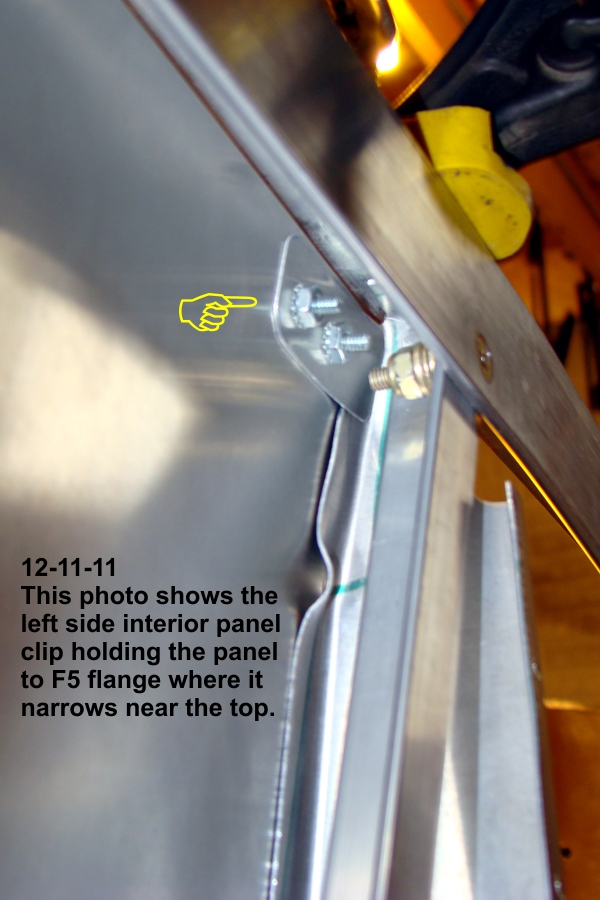
I then removed these skins so I could work on creating the interior side panels that go between F3 & F5 bulkheads. These panels will be made so I can remove them to have access to the landing gear bolts and rudder pedal cables.

In the series of photos below, you can see that I created a tab at the top of these panels that will sandwich the F5 bulkhead flange near the top. On my bulkheads, I found that the F5 flange becomes too narrow for me to install screws. This tab will make the panel fit snugly with the flange at the top.


In the photo below, you can see that I also created an angle from some .032 aluminum stock to hold the bottom edge of the panels in place. I slid these angles between the floor skin and the outer floor ribs so they can share the same rivets.


I still have some work on all of the above and should have pictures of the final product in the near future.