Wednesday, February 22, 2012

Get Smart use to say: "Missed it by that much."

When you make mistakes, you just find solutions. As I build a piece or build a part, I always try to anticipate how this step is going to effect things down the road. Sometimes you understand the cause and effect, and sometimes you don't. I built my fuel tank about a year ago.  There has been some modifications to the tank plans and I have 3 plan revisions to work from. The original tank was only 9.5 gallons, but that wasn't large enough for some builders, so Dave Thatcher created a 10.5 gallon drawing for someone and I got a copy of this. Then when the Europe equivalent of the FAA didn't like how Dave had installed his tank, Dave modified the tank and how it was installed/mounted. At about the same time, Dave developed the floor mounted rudder pedals; again in response to a Europe request. The fuel tank dimensions changed with these modifications, but remained a 10.5 gallon tank. I had bought the hanging rudder pedals and after reviewing the floor mounted version, decided to stick with the hanging pedals. My plan was to use version 1 of the 10.5 gallon tank but use the new mounting method which involved side to side straps that would cradle the tank from underneather. The tank cover would be sandwiched between 2 gaskets at the fuel filler flange. Everything was going to plan until I rasied the tank top to be level with the flanges where the tank cover would be attached. That's when "I missed it by that much." I found my tank corners sticking out beyond edge of the fuselage.

click on image to enlarge

So, in a panic I called Dave and then a local friend, Steve Bennett who stopped by to see what could be done. Between the conversations I had with these two, a "plan B" was developed. I would simply buy longer bolts to lower the tank and I would create a strap to go over the top of the tank to hold it in place. I would then create a fuel access door for the tank cover. This seems to be working out and no snags have presented themselves.


First, I came up with a paper pattern for the top strap that I liked and transfered it to some scrap .020 aluminum. I cut out the perimeter using my band saw. Then I clamped the piece to a scrap board, drilled a hole in the interior and cut the circle out using a jig saw. The .020 aluminum is a little flimsy so I used the board to help with filing the edges.


Once the piece was cut and filed, I mark the locations where I wanted bends and proceeded to make the bends one at a time. I would trial fit the piece after every bend and mark the next bend location. The bottom photo is the final product. I drilled & tapped two holes on each side in the upper longeron for 8-32 screws. To help spread the load, I created two 1/16th inch thick plates to go on top of the strap on each side (as shown in the above photo).


This photo shows the top strap installed. I plan to install aluminum tubing over the 4 bolts that hold the lower straps on so that the nuts can be tighten. The tubes would serve as spacers and this would essentially trap the tank in place.

I'm thinking about creating a cup of some sort to go under the fuel cap flange to catch any drops of fuel so they don't spill inside the cockpit. Look for an update describing what I came up with.  I have an automotive gas cap door on order as I felt this might make a more "professional" installation than me making one myself.

In concert with the installation of the tank, comes the installation of the hanging rudder pedals, but that's the topic for my next post.

Sunday, February 19, 2012

Still working, but no pictures

I haven't posted for a while, but I have been working on the plane. I just haven't taken the time to post anything. Once I get to a good point I'll post some pictures, but not tonight.

I have been working on installing the fuel tank and rudder pedals. This is tedious work, but I'm making progress.  Stay tuned...

Wednesday, December 21, 2011

Forward skins and cockpit work.

I have have been making progress on the forward fuselage in recent weeks. I installed the floor ribs and then the floor skin was cut, bent, shaped and rivet holes drilled in preparation for its installation. In the 3rd photo below you can also see that I created the center control cover which is held in place by screws instead of rivets so it can be removed.

Click on images to enlarge


Next came prepping the side skins for installation. (These side skins were cut and sized last winter when the fuselage was still on the table.) This is a tedious process as you have to fit, remove, mark the hole locations, then drill holes in one piece, then debur them all. Then repeat the process with the adjoining piece until you have what you are looking for. I countersunk the lower longeron near the spar and dimpled the skin for flush rivet installation where the leading edge rib will be mounted later. I also creased any overlapping skin edges in hopes for a smooth, gapless edge once the rivets are installed.


I have yet to drill the rivet holes near the firewall or along the upper longeron as I still have work to do in these areas.

I then removed these skins so I could work on creating the interior side panels that go between F3 & F5 bulkheads. These panels will be made so I can remove them to have access to the landing gear bolts and rudder pedal cables.

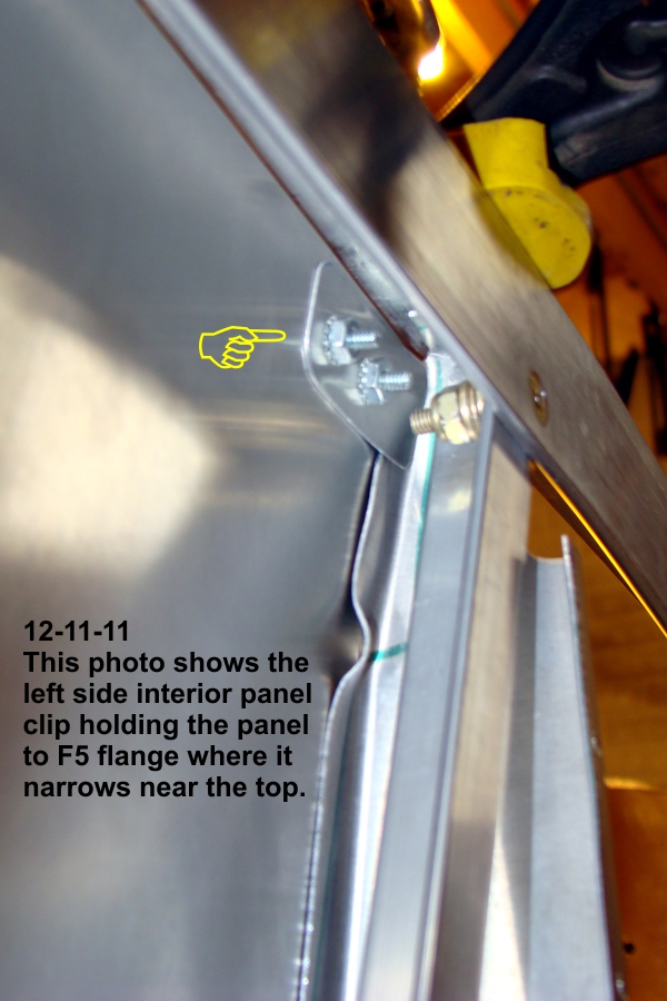
In the series of photos below, you can see that I created a tab at the top of these panels that will sandwich the F5 bulkhead flange near the top. On my bulkheads, I found that the F5 flange becomes too narrow for me to install screws. This tab will make the panel fit snugly with the flange at the top.


In the photo below, you can see that I also created an angle from some .032 aluminum stock to hold the bottom edge of the panels in place. I slid these angles between the floor skin and the outer floor ribs so they can share the same rivets.


I still have some work on all of the above and should have pictures of the final product in the near future.

Tuesday, November 15, 2011

I have a new set of wheels!

Click on image to enlarge


It's a big moment when you get to sit in your creation and and make engine noises! But let's back up and see how I got here.

Once the gear was in place, it was time to assemble the wheels, axles, brakes and wheel pant bracket. I bought everything shown in the pictures below from Great Plains Aircraft Supply. I had drilled the 4 mounting holes months ago. The caliper housing comes to you fresh from the casting mold and needs to be "machined" to allow the calipers to fit inside snugly, but able to slide side to side nicely with out binding. You just use a combination of files and sanding tubes to slowly remove just the right amount of material to get the fit you want.


My axles had a "knob" on the back side of the mounting plate the same diameter as the axle. This is used in other installations, but not on the CX4. You have to grind this "knob" off to make the back side of the axle mounting plate completely flush. I didn't take a photo of this, but you'll figure it out if your axles come with the "knob".

There is a lot of assembly and dis-assembly in this process. You have to create a spacer to keep the wheel the correct distance away from the mounting bolts so as not to rub them on the brake disk. I used a piece of PVC tubing to cut a sample spacer until I found the distance I liked. My spacers were 1.75" long and I made them from .759" ID 4130 steel tubing. I would say this gave me a clearance of approximately 1/8".


Once you have everything the way you want them, you disassemble everything so you can pack the wheel bearings with grease. When you are done with that, you reassemble everything and mark a dot on the axle threads where you want to drill a cotter pin hole to hold the castle nut in place. I was told to only hand tighten the castle nut. Over tightening doesn't allow the wheel to rotate freely.

Also in the photos you can see the piece of aluminum where the wheel pants will be attached later. I used the pattern from the plans and found I had to modify them slightly to fit around my brake assembly. No big deal though.

Next I finished installing the tail wheel. When you tighten the forward bolt it will dent the bottom fuselage skin slightly. This is normal according to Dave Thatcher. I spent an afternoon trying to figure a way to avoid the dent, but the solution eluded me. Mine will have the dent like Dave's does. It is so minor that when you turn it over you don't know it's there.


Now it was time to turn it over! My son was the first to sit in it and he liked it. Then it was my turn. Here is where I get to caution the rest of you. It is best not to put too much weight on the seat area until you have attached the side panels. Why you ask? Because when I stepped on to the spar with one foot I heard a loud bang! I took my foot off and looked around and everything seemed to be in place. So I tried again. This time when I place my second foot on the spar I heard another loud bang! I step off and looked around. I still didn't see anything wrong. So I tried again to get in and this time there were no annoying sounds, but when I sat down and look forward, I could see that the single rivet at the top of each F5 bulkhead had popped free from the top longeron. I decided I needed to go on a diet.

I got out and found my two long wood clamps and pulled the lower and upper longerons together and drilled out and replaced the two rivets. I used longer rivets as well. I'll have to wait until the side skins have been installed to make engine noises again.

I have started installing the forward floor ribs so that will be my next update.

Monday, October 31, 2011

Attached forward bottom skin.

I finished shaping and attaching the forward bottom skin. I dimpled and installed flush rivets along the forward edge so that the cowling will lay across it smoothly. The sides are attached in this manner as well because the side skins overlap in this area. The only difference is that I dimpled the bottom skin and countersunk the longeron underneath.


Click on image to enlarge

I'll begin to install the wheels and brakes so I can then turn the fuselage over.

Monday, October 10, 2011

Began landing gear installation.

I began installing the landing gear. I use a laser I bought at Harbor Freight as my main alignment tool. It has magnets on it, so I attach it to a long handled clamp and clamp the clamp to a small work table and place it in front of my project. I use it to align all the center lines from front to rear. I also used a tape measure to check all distances to the tail wheel bolt in the rear. Once I had everything where I thought it should be, I clamped the landing gear to the lower stingers with 4 clamps.

I should mention that I did this twice. The first time was see where the hole locations should be. I then removed the landing gear and drilled 1/8" pilot holes in it with my drill press. Then I re-aligned the gear and drilled those pilot holes through the stringers in the fuselage. Even though I used 4 clamps to hold the gear in place, I also used 1/8" bits, AN3 & AN4 bolts to place in the holes while I enlarged the holes to their final size to accept an AN5 bolt. The idea here is to make sure the holes stay aligned while you are enlarging the other holes. Here are a couple of photos.


Click on image to enlarge

I had seen in other builder photos indicating one needs to be aware of possible interference of the side bolts that hold the side angle support in place between F3 & F5 bulkheads. I happened to be using pan head screws instead of countersunk screws at these locations, so I will be able to remove these screws temporarily to install the gear bolt nuts. Here are a couple of photos showing this situation.


I just noticed that I have mislabled the locations of these bolts. They are the right side, but I have the forward/rear locations reversed from what they should be.

Thursday, October 6, 2011

Installing forward bottom skin.

The last two weekends I have continued working on the forward bottom skins. Everything is going fine, but there is a lot of trial fitting and trimming that has to take place before actually pulling rivets. I have also been preparing to install the landing gear by drilling pilot holes in the gear in preperation to locate it on the fuselage and transfer the hole locations to the lower longerons.

Here are a few photos. As always, look in my photo album for additional photos.