Click on image to enlarge
Sunday, January 27, 2013
Thursday, January 17, 2013
Fuel Lines, Gascolator & other stuff
It's been a while since my last post, but I have been working on my project. I installed my fuel lines, tank drain and mounted the gascolator to the firewall. I'm using poly fuel lines on the back side of the firewall as they are flexible, inexpensive and easy to work with. I didn't want to go through the firewall with my tank drain because I thought it added complexity, so I found a suitable spot on the floor behind the firewall and mounted it there. I did use a piece of .032 aluminum for reinforcing the floor as I will use this drain to check for water in the fuel during preflight. The photos below show the results of my labor.
Santa came through this year with an Aircraft Spruce gift card for which I used to purchase an MGL E3 engine monitor. I guess I was a good boy in 2012!
Click on image to enlarge photo
On the front side of the firewall I had a 12" braided fuel line I had left over from a previous project and I found a exact match of it at Auto Zone On-line. This is way cheaper than to have them custom made. I also had some left over fire sleeve that I used to wrap them. I use stainless tie wraps that I found at the auto parts store to secure the ends of the firewrap.
I have been doing other work as well. I have been rewiring my iCom A200 radio tray with new aviation wires. I find this to be necessary, but tedious work.Santa came through this year with an Aircraft Spruce gift card for which I used to purchase an MGL E3 engine monitor. I guess I was a good boy in 2012!
Monday, December 3, 2012
Brake Lines & Fuel Pumps
I have been working on my project, but sometimes you get caught up in the details and it doesn't seem like you're making any progress. In fact, you are, because attention to the details makes a better aircraft.
I needed to run my brake lines though the lightening holes in the F2 bulkhead and they were rubbing against the edge. Later I will be running wiring through this bulkhead also. So, I went looking for an edge trim material and finally saw a nice solution on another builders CX4. I can't remember who it was, but thank you! You can see it in the photo above. It is called Grommet Strip and I purchased it from Terminaltown.com as suggested by the other builder (Item #GSNC-1). It comes in two sizes and this one works on material up to a thickness of .036". I ordered 4 feet and was hoping it came in one piece so I could cut it to length. Unfortunately, it came as four, one foot pieces. It is designed for circular holes for which the F2 bulkhead holes are not. They are made of a hard plastic and rely on the memory of the material to stay in place within a circle hole. This might work for our oblong F2 bulkhead holes if it came as one piece, but it takes two pieces of the 12" strips to fill the circumference. To help keep it in place, I used some of the high temp clear caulking I was using to fill the holes around my firewall edge. The caulking keeps the trim in place quite nicely.
This next photo shows the F2 bulkhead from the rear. You can see that I used a larger tube to protect the brake line where it comes through the F2 bulkhead and 3 layers of heat shrink to protect it from the upper longeron hole it goes through. There is little to no movement at the point it goes through the longeron, but I wanted some protection from rubbing anyway.
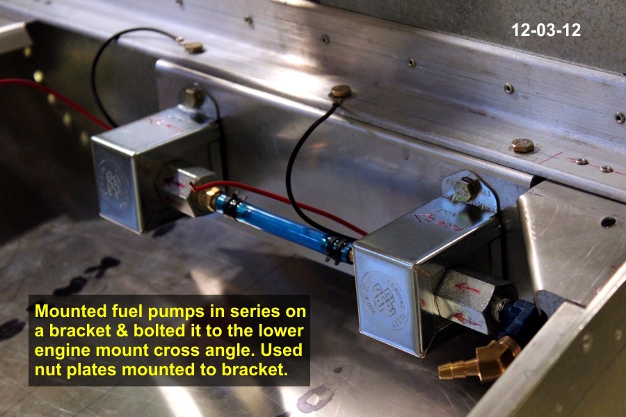
I have been working on my fuel system also and decided on installing two pumps in series. To minimize vapor lock situations, I also decided to install them on the back side of the firewall where they will remain cooler. Instead of mounting them directly on the firewall, I created a mounting bracket from some scrap .062 aluminum I had laying around. I just bent a 90 degree flange as a mounting point. I drilled 3 holes in the lower engine mount cross angle for AN3 bolts and installed nut plates on the underside of the bracket flange so that it could be removed to work on or replace a pump. The photos below show this installation.
Up next is the gascolator installation and running the fuel lines through the firewall.
click on image to enlarge
This next photo shows the F2 bulkhead from the rear. You can see that I used a larger tube to protect the brake line where it comes through the F2 bulkhead and 3 layers of heat shrink to protect it from the upper longeron hole it goes through. There is little to no movement at the point it goes through the longeron, but I wanted some protection from rubbing anyway.
I have been working on my fuel system also and decided on installing two pumps in series. To minimize vapor lock situations, I also decided to install them on the back side of the firewall where they will remain cooler. Instead of mounting them directly on the firewall, I created a mounting bracket from some scrap .062 aluminum I had laying around. I just bent a 90 degree flange as a mounting point. I drilled 3 holes in the lower engine mount cross angle for AN3 bolts and installed nut plates on the underside of the bracket flange so that it could be removed to work on or replace a pump. The photos below show this installation.
Up next is the gascolator installation and running the fuel lines through the firewall.
Thursday, October 25, 2012
Tank Cover & Front Skin ready for rivets
I finished the tank cover and I'm ready to pull rivets for the side skins and instrument panel top skin. However, I will not pull the rivets in hopes that Santa will bring me some more instruments. It just seems to me that waiting till the very last moment to shut this area up is the best way to proceed. I also want to work out my fuel pump locations and not having the side skins in place would also allow for more working area. Here are a few photos.
Click on image to enlarge
The photo below shows I also installed my electical bus on the front side of bulkhead F2.
I have more photos in my photo album if you would like to view them.
Next I will be working on the tail feathers and writing my wish list to Santa.
Saturday, October 6, 2012
Finished installing fuel filler door.
I finished installing my fuel filler door today and I am quite satisfied with my creation and work. Here are a few photos:
Click on image to enlarge
I was concerned that the door would not line up with the cover skin and in the corners it did not. However it was quite simple to bend the corners slightly with my fingers and thumb to get the door to match up nicely with the cover skin.
Next up is to finish installing the tank cover skin itself and then on to the skin that spans F2 to F4.
Tuesday, October 2, 2012
Creating a Fuel Filler Door
If you remember, I created a fuel tank that would not fit under the tank cover skin and have the filler cap exposed as the plans call out for. Instead I had to lower the tank and now have to create a door to expose the fuel filler cap. Here are a few photos of what I'm working on.
Click on image to enlarge
I settled on a 5"x5" opening in the shape of a "D". I looked into using a DZUS or Camloc fasteners but they both require a relatively expensive specialized tool for inserting the grommets. I bought a Hartwell H-5000-2 latch from eBay but once it arrived, I discovered I didn't have the necessary clearance between the tank cover skin and the tank for it to be used. So I searched the internet and found a rotating, spring loaded latch that I thought would work for this application. I found it at Granger and it came in three sizes. The medium sized one is the one I purchased (part # 4RPY8) for about $10.00. Here are a couple of photos showing it in the open & closed positions.
This is what it looks like from the top.
As you can see, it has a very low profile as well.
I made the supporting shelf from two layers of .032 aluminum. I had to use two layers in order to account for the thickness of the door hinge which was .032 as well. Once I got the two pieces shaped the way I wanted them to be, I used spray adhesive to hold the two pieces together until they could be riveted into position around the door opening. You should be able to see the two layers in the 1st photo above. Here are a some photos of the door temporarily in place.
Next up is to drill and rivet the shelf and hinge to the tank cover skin then to finish the installation of the skin itself. The door will need a slight arch in it to match the curve of the skin. Wish me luck on figuring this out.
Friday, September 28, 2012
Installation of my radio tray.
I finished the installation of my radio tray for my iCom A200 radio. The photos below show that I tried to make it as removable as possible from below because once the skin between F2 & F4 (the instrument panel) is riveted in place, the only access is from below or through the openings in the F2 bulkhead.
Click on image to enlarge
I attached a 1.5" x.0625" angle, purchased from Lowe's, to each side of the tray because the tray itself could not be attached from below. The tray mounting holes were on the sides. I removed some material from the angles to lighten it and to create clearance for other instruments. Then I used an aluminum channel, also purchased from Lowe's, as a rear tray support that spans width wise between the upper longerons. I used nut plates on both the tray angles and the channel so the screws could be removed from below. In the front, I stuck some window foam insulation to the tray's underside which allows it to rest on the angle I'm using at the bottom of the panel for my switches and breakers. This puts the tray at the approximate height behind the panel hole where the radio slips in from the front. I left the screws at the rear channel slightly loosened until the radio is in place and then I'll tighten the screws at the rear support.
This is how it looks from the front.
I'm currently working on the fuel tank cover and a hinged access door for the fuel filler. I'll have another update to document this progress soon (I hope).
Subscribe to:
Posts (Atom)